If you’re an architect, kitchen designer, or serious DIY remodeler, a pot filler faucet CAD drawing is the single document that keeps your range wall from becoming an expensive mistake. It tells you precisely where the water line lands inside the wall, how far the double-jointed arm swings, and whether the spout will actually clear a tall stockpot. Below, we’ll cover where to get real CAD blocks, what every dimension on them means, and how to spec a pot filler that fits your range and your rough-in — with concrete numbers you can build to.
What exactly is a “pot filler faucet CAD” file, and who needs one?
It’s a scaled digital drawing of the faucet — geometry only, no marketing gloss — that drops into your floor plan or elevation at 1:1 scale. Designers, plumbers, and general contractors use it to coordinate the water supply rough-in, tile layout, and range placement before a single hole is cut.
You’ll typically see three formats offered on a manufacturer’s product page:
- .DWG / .DXF — the classic AutoCAD 2D blocks, both plan view (looking down) and elevation (looking at the wall). This is what most plumbers and drafters actually open.
- .RFA (Revit family) — a parametric 3D BIM object with the connection point, arm articulation, and metadata baked in. This is what commercial and higher-end residential firms drop into a BIM model.
- .PDF spec / cut sheet — not editable CAD, but it carries the same dimension callouts and is the fastest sanity check for a homeowner.
If you’re doing a one-off kitchen and just want the rough-in height, the PDF cut sheet is usually enough. If you’re modeling the whole kitchen or handing plans to a plumber, pull the real DWG or RFA so the dimensions are locked and can’t drift when someone eyeballs a photo.
Where do I download a real pot filler CAD block — and why not just scale a picture?
Download it straight from the manufacturer’s “Resources,” “Downloads,” or “Technical Drawings” tab on the specific product page — that’s the only source guaranteed to match the SKU you’re buying. Reputable brands, including us at faucitta, publish DWG, PDF, and often Revit files per model. Never scale a product photo: camera lens distortion and perspective can throw the swing radius off by an inch or more, and an inch is the difference between a pot filler that clears your pasta pot and one that bangs into it.
A quick, reliable workflow to get the right file:
- Find the exact model number (it’s on the spec sheet or the box), not just “pot filler” — different arm lengths share a family name.
- Open that product page’s downloads section and grab the format your software reads (DWG for AutoCAD, RFA for Revit).
- Cross-check the drawing’s title block: it should list the model number, the rough-in inlet size (almost always 1/2″ NPT), and a revision date.
- If a CAD file isn’t posted, email the manufacturer’s spec/technical team — they’ll send it. A brand that can’t produce a dimensioned drawing is a red flag for build quality.
What dimensions on the CAD drawing actually matter for placement?
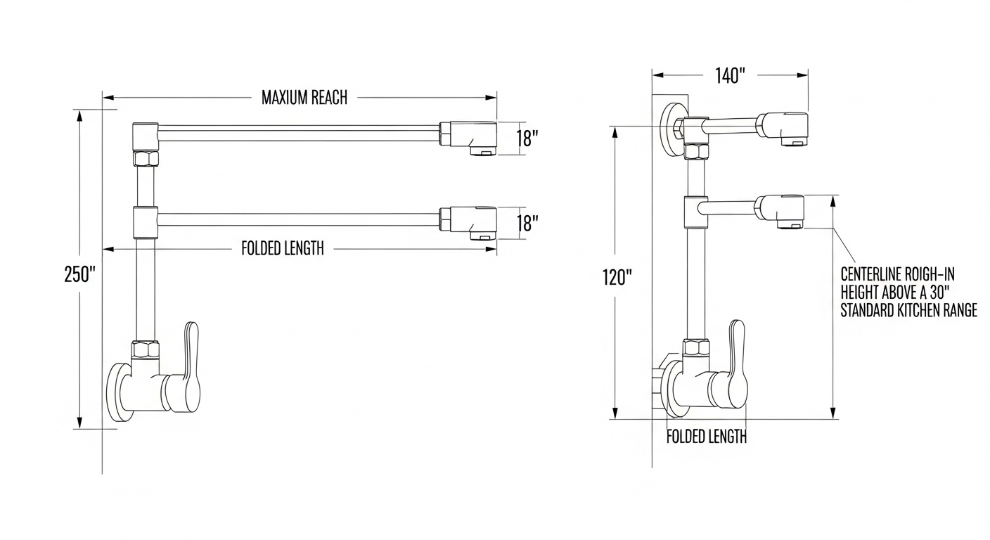
Four numbers decide everything: the rough-in centerline height, the maximum reach (extended arm), the folded/retracted depth, and the inlet connection. Read those first; the rest is detail.
Here’s what each callout means and how to use it:
- Rough-in centerline height: where the 1/2″ supply stub exits the wall. For a standard 36″ range, most pros set this so the finished faucet body sits roughly 4–6 inches above the cooktop surface — commonly a rough-in around 20–24 inches above the finished counter, but always follow the specific model’s sheet.
- Maximum reach: how far the spout tip travels from the wall when the double-jointed arm is fully extended — typically 18 to 24 inches. This must cover the center of your largest front and back burners.
- Folded depth: how far the faucet projects when tucked flat against the wall (often 2–4 inches). Matters for backsplash tile and for not clipping a range hood.
- Swing/coverage arc: the drawing usually shows the arc the spout sweeps. Overlay it on your burner layout to confirm every pot position gets water.
- Inlet size and type: nearly always 1/2″ NPT female or a 1/2″ copper sweat connection — verify so your plumber roughs in the matching stub.
Because a pot filler is a wall-mounted faucet with a long horizontal spout, spout reach is the make-or-break spec — the same principle we dig into for other wall-mounted styles in our guide to what a 6″ spout reach wall mount faucet really means. A pot filler just pushes that reach much further because it has to travel out over the burners.
What’s the right mounting height above a range?
Set the finished spout so it clears your tallest routine pot with the lid on — for most kitchens that means the faucet body about 4 to 6 inches above the cooktop, which usually puts the rough-in stub roughly 20 to 24 inches above the finished counter. Then verify against the CAD file, because the arm’s pivot point adds height the raw wall measurement won’t show.
The practical test: measure your biggest stockpot, add clearance for lifting it on and off the burner, and make sure the spout tip sits above that line when extended. Too low and you can’t slide a tall pot underneath; too high and water splashes as it falls. A CAD elevation lets you simulate this exactly instead of guessing on site.
One more coordination note: the pot filler shares the range wall with your hood, backsplash, and sometimes upper cabinets. Drop the CAD block into your elevation alongside those elements so you catch a collision on screen — not after the tile is grouted.
Which pot filler CAD format should I use — DWG, Revit, or PDF?
Use DWG/DXF if you draft in AutoCAD or a 2D program, Revit RFA if you work in BIM, and the PDF cut sheet if you just need to hand a dimension to a plumber. Here’s how they compare:
| Format | Best for | Contains | Editable? | Who typically uses it |
|---|---|---|---|---|
| DWG / DXF (2D) | Floor plans & wall elevations | Plan + elevation geometry, dimensions | Yes, full CAD editing | Drafters, plumbers, GCs |
| Revit RFA (3D BIM) | Full 3D coordination | 3D geometry, connection point, metadata, articulation | Yes, parametric | Architecture/MEP firms |
| PDF cut sheet | Quick reference & approvals | Dimensioned views, specs, finish options | No (view only) | Homeowners, showrooms |
| SketchUp / SKP | Design visualization | 3D model, often textured | Yes | Kitchen designers |
For most residential remodels, the DWG plan-and-elevation pair plus the PDF is all you need. Save the Revit family for projects that live inside a BIM model where the plumbing contractor is pulling connection points straight from the object.
Single-joint vs. double-joint pot filler — what does the CAD show?
A double-joint pot filler has two pivot points so the arm folds flat against the wall and extends far over the burners; a single-joint (or “swing-arm”) design has one pivot and a shorter, simpler reach. The CAD drawing makes the difference obvious: a double-joint block shows two arc segments and a much longer extended reach.
- Double-joint: folds to 2–4 inches deep, extends 18–24 inches. Best for wide ranges (36″+) and cooks who use back burners. The most common choice.
- Single-joint: simpler, fewer seals to fail, but shorter reach — fine over a compact 30″ range where the burners sit close to the wall.
Whichever you pick, the CAD swing arc is your proof of coverage. Lay it over the burner grid and confirm the spout reaches the far burners before you commit the rough-in. If you’re still deciding whether a pot filler belongs in your kitchen at all versus relying on your main faucet, our breakdown of how kitchen and bathroom faucets really differ is a useful primer on matching a faucet’s flow and reach to its job.
How do I go from CAD file to a finished, leak-free install?
Match the rough-in stub to the drawing, pressure-test before you close the wall, and mount to solid blocking — the CAD file gives you the target, but the install has to hit it. Because a pot filler sits directly above heat and gets used with heavy pots, the wall connection has to be dead-on and well supported.
- Rough-in to the CAD centerline: your plumber sets a 1/2″ supply line to the exact height and horizontal position shown on the drawing. Add in-wall blocking behind the mounting point so the faucet isn’t hanging on drywall alone.
- Add a shutoff: put an accessible shutoff valve on the supply line so the pot filler can be isolated without killing water to the whole kitchen.
- Pressure-test open: before closing the wall, pressurize the line and check the joint. A leak behind finished tile above a range is a nightmare to reach.
- Mount and seal: thread the faucet to the stub with the manufacturer’s specified sealant or gasket, then check the escutcheon sits flush to the tile.
- Cycle the joints: extend and fold the arm fully several times, watching for drips at each pivot. Pot filler leaks almost always show up at the joints, not the wall.
If you’re weighing whether a plumber is even necessary, remember that the water connection is the part worth paying for — the mounting and cosmetic assembly is DIY-friendly if you’re comfortable, similar in spirit to jobs like a pull-out kitchen faucet hose replacement that many homeowners handle themselves.
Do budget pot fillers come with usable CAD files?
Mid-range and premium models almost always publish full CAD packages; ultra-cheap import brands often don’t, which is itself a warning sign. If a pot filler under $150 has no dimensioned drawing anywhere, you can’t reliably rough it in — and that missing document usually signals thin castings and low-grade cartridges too.
You don’t have to overspend to get a well-documented faucet, though. The same “buy documented quality, not the cheapest thing on the shelf” logic we apply to affordable kitchen faucets — see our pick for the best budget Moen kitchen faucet under $200 — applies to pot fillers. Look for a solid-brass body, a published DWG/PDF, ceramic-disc valves, and a real warranty. Those four together tell you the drawing you’re building to reflects a faucet that will actually last over a hot stove.
Author note & why you can trust this spec guidance
This guide was written by the faucitta product-engineering and technical-documentation team, the same group that produces our published CAD and spec sheets. faucitta manufactures and supplies faucets and bathroom fixtures with dimensioned DWG, PDF, and Revit files released per SKU, so specifiers can build to real geometry rather than guesswork. Our pot filler bodies are lead-free brass and our valves are pressure- and cycle-tested to standard industry endurance benchmarks (typically 500,000+ cycles) and backed by a limited lifetime warranty on the faucet body and finish. When a dimension on our drawing says 22 inches of reach, we’ve verified it on the bench — because a CAD file is only as trustworthy as the testing behind it.
FAQ
Is a pot filler faucet CAD file free to download?
Yes. Reputable manufacturers, including faucitta, provide CAD and spec files at no cost from the product page’s downloads tab. You may need to enter an email or create a free account on some sites, but you should never have to pay for a manufacturer’s own technical drawing.
What file format do plumbers actually want for a pot filler?
Most plumbers and drafters work from a 2D DWG or DXF, or a PDF cut sheet with clear dimensions. Revit RFA files are for architects and MEP engineers modeling in BIM. If in doubt, send both the DWG and the PDF — the PDF is universally viewable and carries the rough-in height every plumber needs.
What is the standard rough-in height for a pot filler above the range?
There’s no single code number — it depends on your cooktop and pot height — but a common target puts the finished faucet body about 4 to 6 inches above the cooktop surface, which usually means a rough-in stub roughly 20 to 24 inches above the finished counter. Always confirm against the specific model’s CAD or spec sheet, since the arm pivot height varies by design.
Does a pot filler CAD file tell me the water inlet size?
Yes. The drawing’s title block or a callout lists the inlet connection — almost always 1/2″ NPT (or a 1/2″ copper sweat connection). Your plumber roughs in a matching 1/2″ supply stub. Confirming this from the CAD file before rough-in prevents a mismatched fitting at install.
Can I use a pot filler CAD block to check if it clears my range hood?
Absolutely — that’s one of its best uses. Drop the folded-position elevation into your kitchen wall drawing alongside the hood and backsplash. Because the CAD block shows the exact projection when retracted (often 2–4 inches), you can spot a collision with the hood or upper cabinets on screen before anything is installed.